2023-02-19
Further Adventures Gaming and Watching (part 1)
Som weeks ago i wrote about my adventures with the new Nintendo Game and Watch with Colour Screen and how I reflashed it. If you have not already read that, you might want to, as it provides some background info. Since then I have done a lot more to make the process of flashing easier and make the Game and Watch better.
A Solid Connection
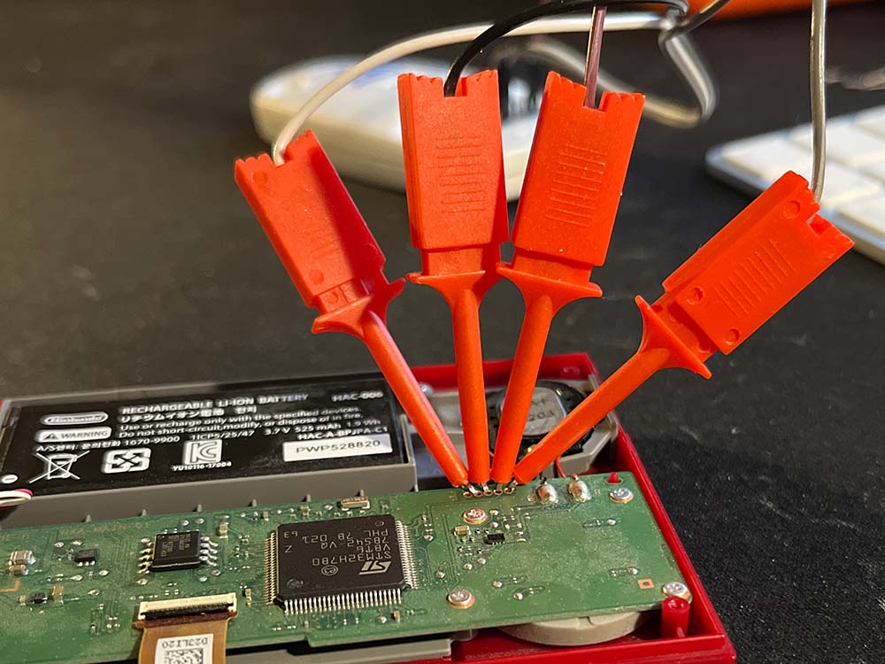
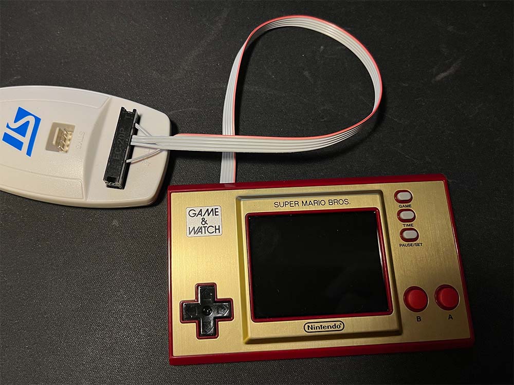
The first thing to fix was a better way of connecting the ST-link V2 programmer to the debug port of the Game and Watch. The hook leads were neither convenient nor practical, and very prone to say click and go flying out of the hole they were supposed to make connection with.
The spacing of the connector in the Game and Watch is 1.27 mm. This is exactly half of the more common 2.54 mm pinheaders, and very tiny. For you Imperial people out there, 1.27 mm is exactly equal to 6/10th poppyseed.
Even though 1.27 mm is not as common as 2.54 mm, pin-headers and sockets are still available. I ordered some from Digikey and received them two days later.
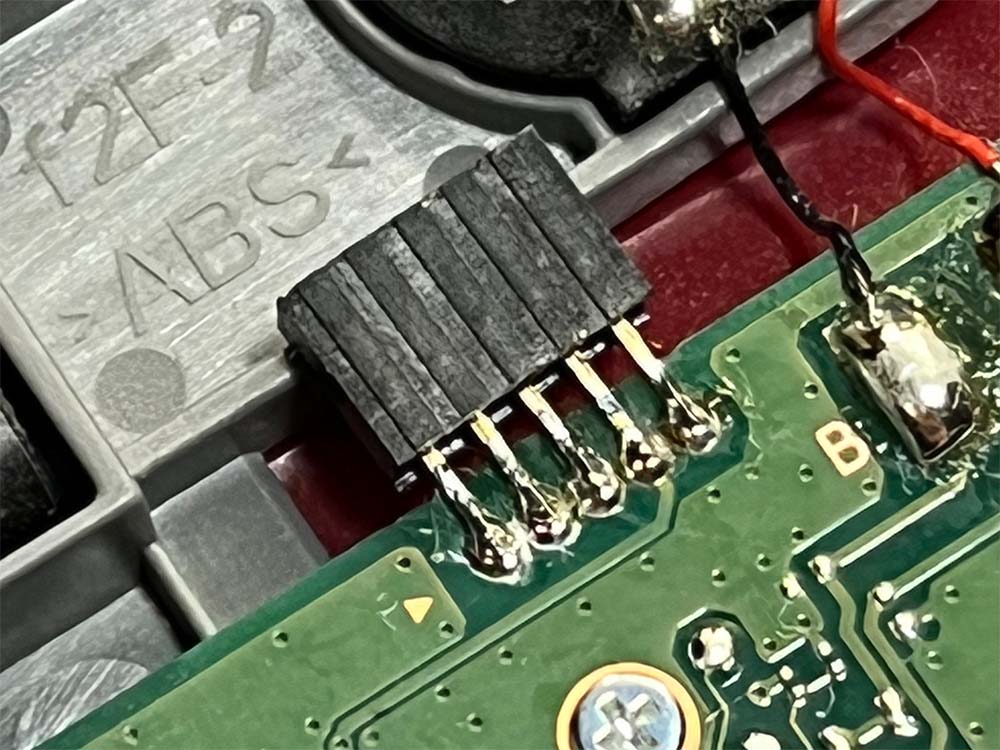
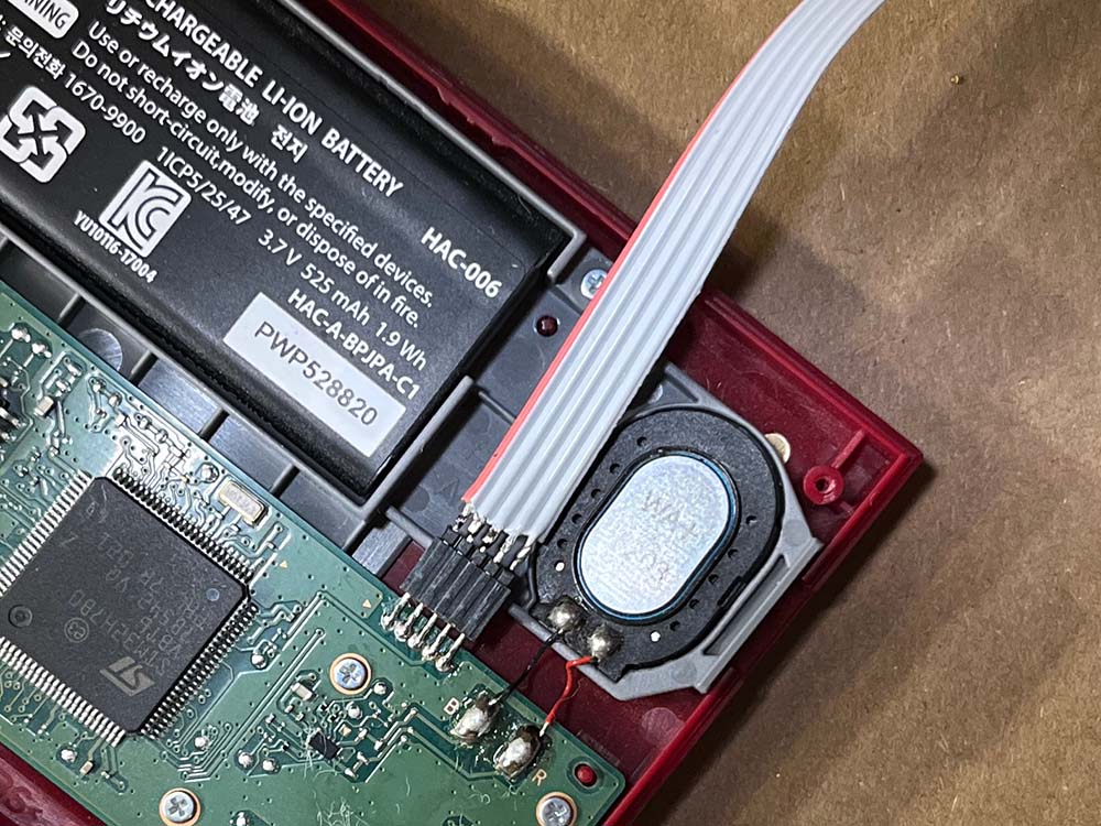
I soldered a socket header to the debug port. This placement means I need to open the back every time I want to connect the programmer, but for now I didn't want to make any holes in the case for external connectors.
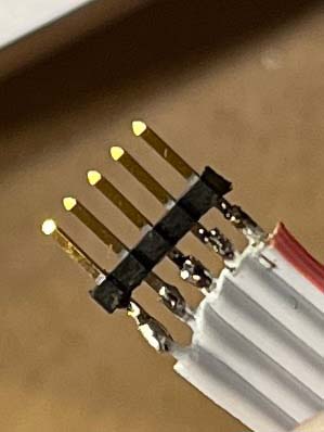
The receptacle part done, I needed a wire to connect it to the ST-link programmer. Standard ribbon cable conveniently enough also has a spacing of 1.27 mm, so we can just use that and solder it to a pin-header that fit our receptacle. Ribbon cables always come in even number of wires, but I wanted five. That's easy enough to fix though, they can just be separated. Then i stripped off a millimeter or so of insulation on one end and clumsily soldered it to a pin-header. It's very easy to melt the plastic in the pin-header, making them crooked, so it helps if the pins are inserted in a socket to hold them in place.
The other end of the ribbon we connect to a normal 2.54 mm 2x10 pin IDC-connector (Insulation-displacement connector-connector). These connectors are specifically made for these kind of ribbon cables, but we have special requirements on the pin positions we put the wires in, so putting it together is a little tricky. The connectors have small forks that cut through the insulation of the wires and make contact. We just need to put the right wire at the right position and gently push it down using our fingernails. When everything is in the right position, we put the cap on the connector and press it with a pair of pliers to make sure the connections are good. Then we measure with a multimeter to make sure it did not accidentally make connections between the wires.
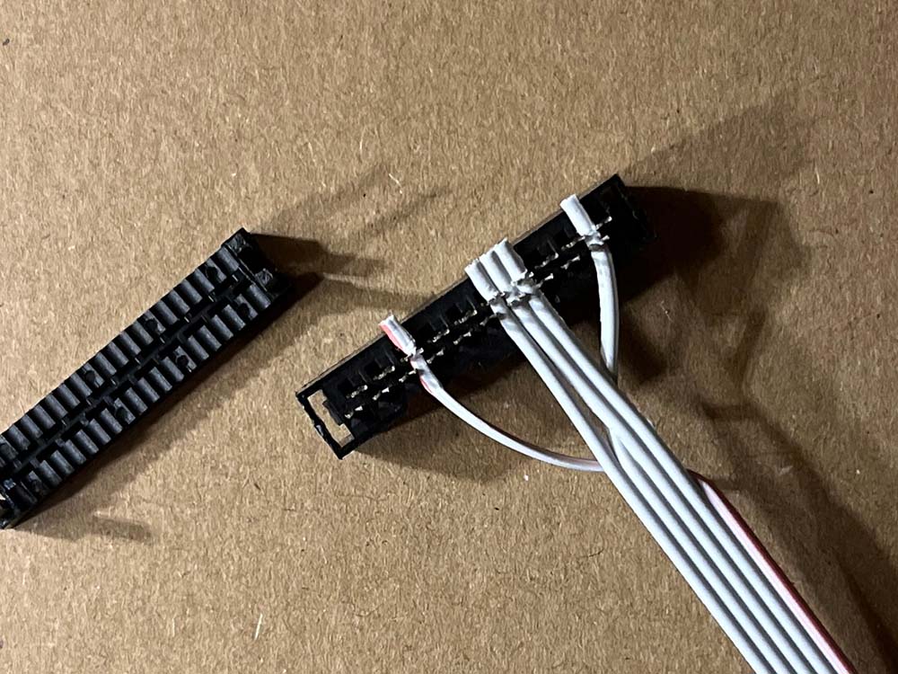
Please make sure the key on the connector, the small bit of plastic that prevents if from going in the wrong way, is on the right side. I did not make that sure and had to remove the wires, turn the connector 180 degrees and do it all again. Fun.
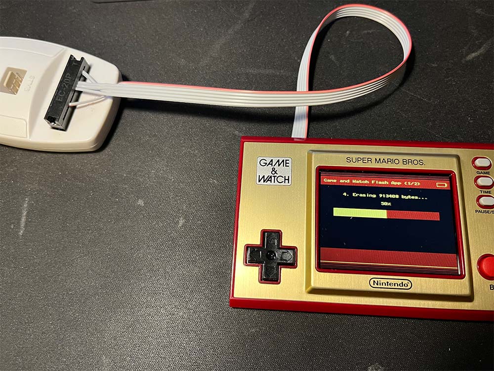
When plugging in, the red wire is pin one, and the little golden triangle indicates pin one.
For reference, the connections between the Game and Watch and the ST-link are:
| GnW pin | ST-link v2 pin | Note |
|---|---|---|
| 1 - NRST | 15 - NRST | Reset (closest to golden triangle) |
| 2 - SWDIO | 7 - TMS_SWDIO | Data |
| 3 - GND | 8 - GND | Ground |
| 4 - VDD 1.8 V OUT | 2 - VAPP | Target VDD, do not connect to power source |
| 5 - SWCLK | 9 - TCK_SWCLK | Clock |
| 6 - Zelda only | N/C | Not connected |
| 7 - Zelda only | N/C | Not connected |
Please note that the VDD-pin on the Game and Watch is outputting 1.8 V. This is the voltage the GnW microcontroller uses. Do not connect this line to any other voltage, you will make things broken if you do. It is connected to the VAPP-pin on the original ST-link v2, which is an input pin that is used to make sure the other pins operate at the correct voltage.
If your interface is not an original ST-link (there are many clones, and they look very similar and can be difficult to tell apart from the real ones) it does likely not have this functionality, and you may get problems when flashing. Also please verify that your non original ST-link does not output voltage on the VAPP-pin. If it does, do not connect that pin.
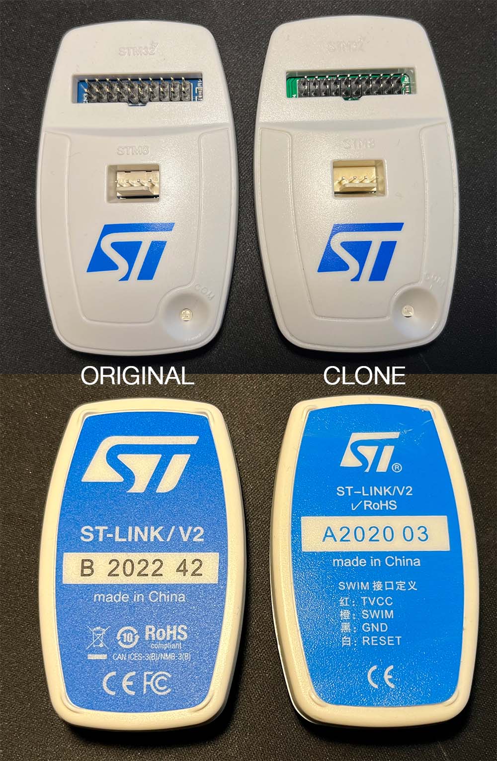
The photo above is a clone I bought two years ago and an original I bought last month. Note that there may be differences in appearance to the ones I have depending on when and where they were made. One major difference between mine are that the year/week on the back is printed in blue as part of the label on the clone, but on the original it has been printer in black at a later time. The only way to be sure what you will get though is to buy from a reputable seller.
A real ST-link will measure the voltage on the VAPP-pin and you can read it on the screen when using OpenOCD software to flash the Game and Watch. It should say 1.8-ish volt.
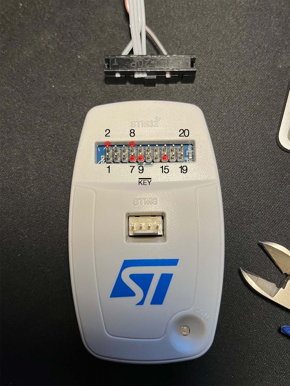
For more info about the pinout, please se the ST-link data sheet. If the ST-link is being helt with the ST-logo the right way up, the key of the 20 pin IDC-connector will be pointing down, and the pin 1 will be to the bottom left.
To Be Continued
This was supposed to just be a little blog entry, but I realise it's basically turning into a tutorial. Anyway, I'm out of time for now, so I will continue next time.
In the next episode we will do some more soldering to replace the flash chip. stay tuned. 😁